| |
SmallPICO
assembly instructions:
The SmallPICO board is pre-loaded with a test sketch and it will blink
all output pins including the user LED.
Before soldering 2 male headers make sure that the SmallPICO board
can blink the user LED with your Arduino IDE.
If it can't, troubleshoot the problem first before going
further.
If you can't blink-a-LED before soldering, you won't be
able to blink-a-LED after soldering.
 |
|
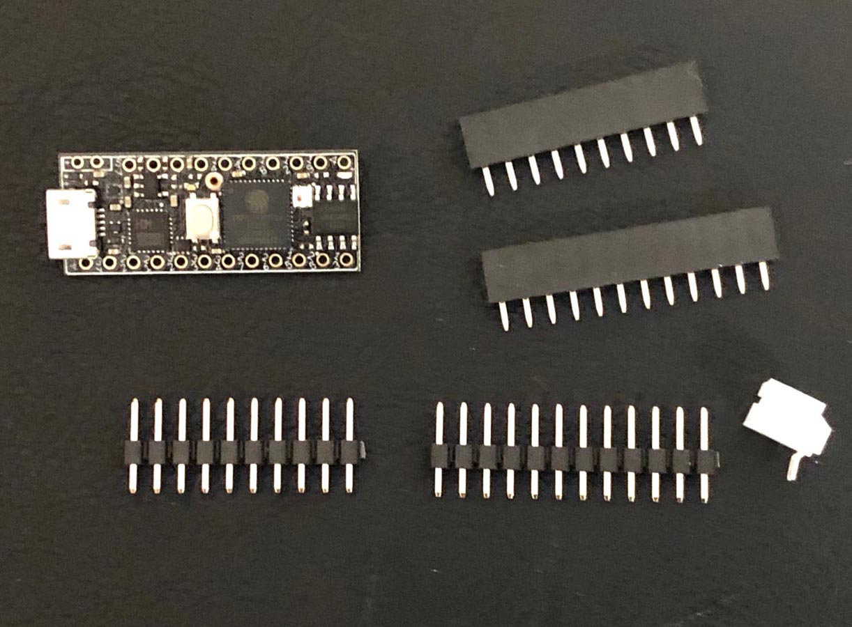
1. Parts included in the package:
One
SmallPICO board.
One 1x10 male header and
one 1x10 female header, both are low profile.
One 1x12 male header and one 1x12 female header,
both are low profile.
One
2-pin JST connector, 2mm pitch.
|
 |
|
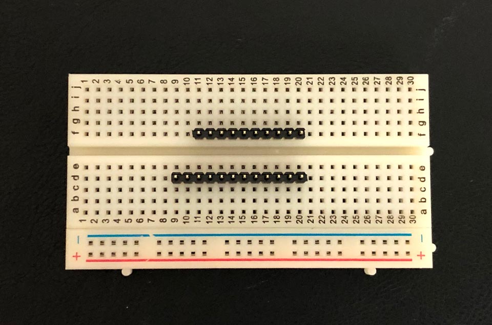
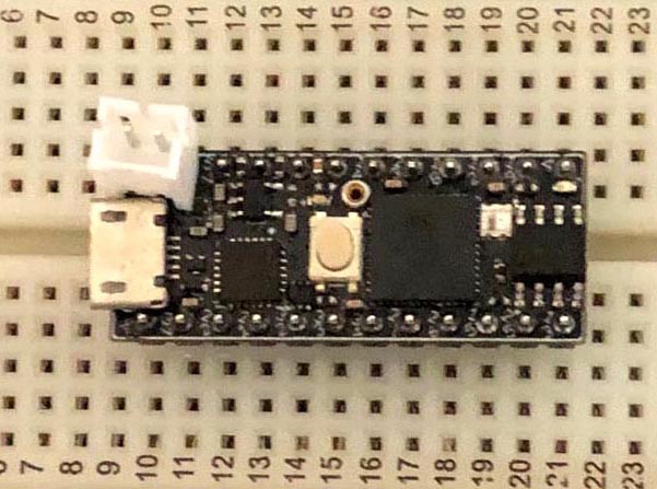
2 Plug two male headers onto breadboard at 0.4"
apart. Make sure it's 0.4" apart, not 0.5"
apart. |
 |
|
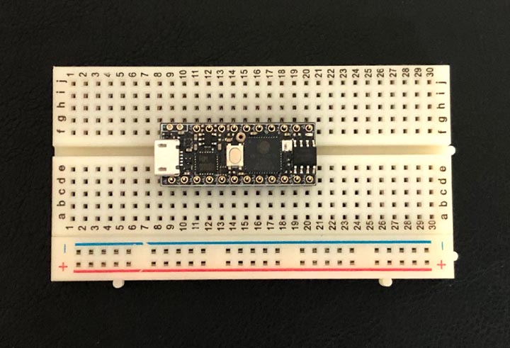
3. Place the SmallPICO board over the two male
headers.
Start soldering 2 pins, pin1 and pin13.
The pin 1 is the ground pin at the low left
corner, the pin 13 is the GPIO04 pin at the up
right corner. Solder pins while pressing
down the board. Once those 2 pins are
soldered, check to make sure there is no gap
between the PCB and the male headers. If not,
you still have a chance to correct it. See
the next picture.
Then solder all other remaining pins.
Be very careful when soldering as some pins are
close to components, don't make solder bridges
or de-solder components. The capacitor below the
reset pin is connected to the reset pin. So if
you make solder bridge on that connection that's
OK. |
 |
|
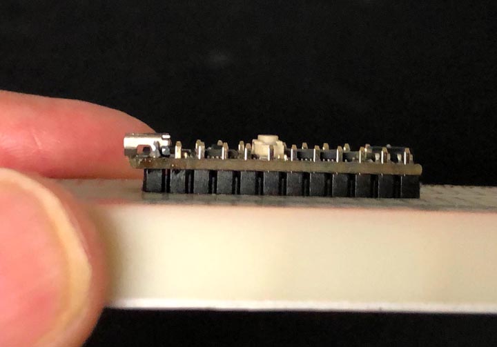
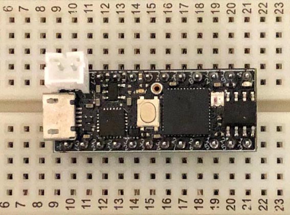
4. No gap between the PCB and the male
header.
|
 |
|
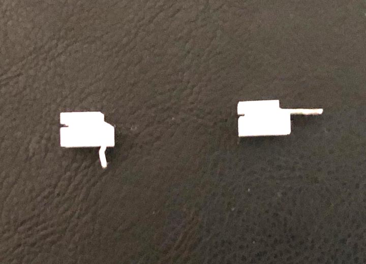
5.
Two pins of the JST connector come in
right-angle. You need to bend the pins and make
them straight.
As shown at left, the left hand side of the picture is the connector
with right angle pins, the right hand side is
the connector with straighten pins after
bending. |
 |
|
6. Then place the connector as shown
at left
before soldering it.
Solder the left pin first. If the connector
is slanted, then twist the the connector
count clockwise to make the connector
perfectly in the horizontal position, then solder the right pin . |
 |
|
7. This is the final assembled board.
Take care of the LiPo battery connector.
When you unplug a battery cable hold the
connector with one hand and unplug the cable
with the other hand. |
 |
|
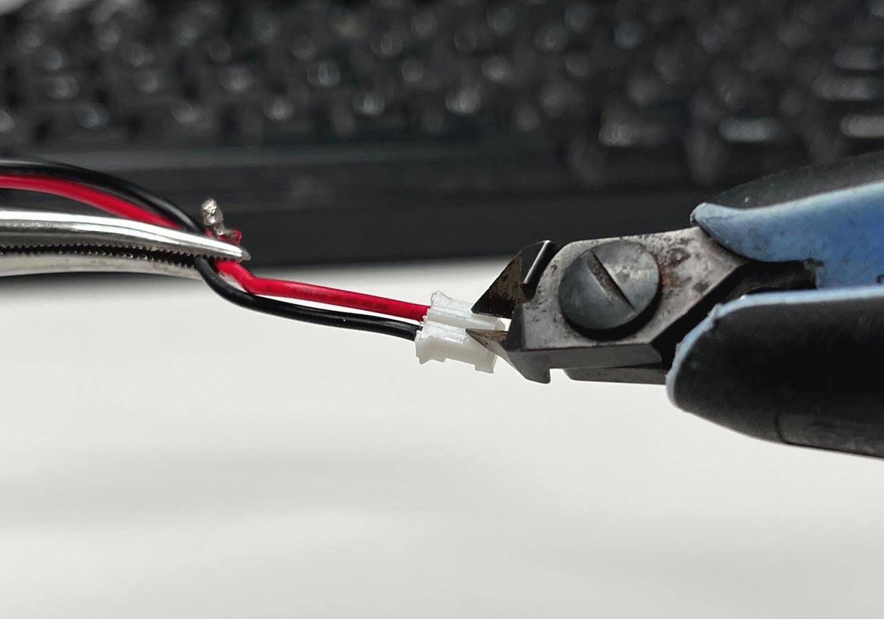
8. Cut off the tab on a battery cable
connector.
Sometimes the the battery connector is too tight
and hard to pull the cable out. You can cut off
the tab in the middle, so you can pull
out the cable from the connector easier.
|
|
|
|
|
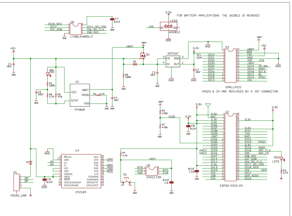
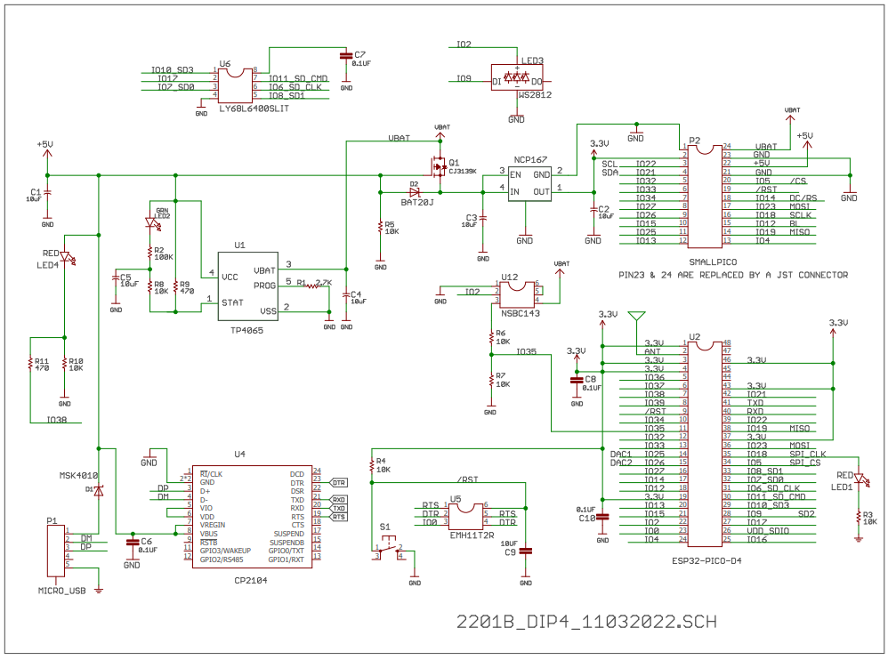
Schematic
Rev.
A
Rev.
B
Example Programs
|
 Trainer4Edu.com
SmallPICO.com
Flappy Bird
Trainer4Edu.com
SmallPICO.com
Flappy Bird